
1. Turbine flow meter operating principle
Turbine flow meter schematic diagram shown in Figure 3-1 . A turbine is placed in the middle of the pipe and both ends are supported by bearings. When the fluid passes through the pipeline, the turbine blade is impacted and a driving torque is generated to the turbine so that the turbine rotates against the conflict torque and the fluid resistance torque. In a certain flow range, the rotational angular velocity of the turbine is proportional to the fluid velocity for a given viscosity of the fluid medium. Thus, the fluid flow rate can be obtained through the rotational angular velocity of the turbine, and then the fluid flow through the pipeline can be calculated.
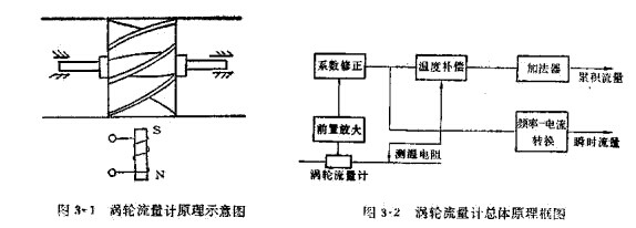
The rotational speed of the turbine is detected by a sensing coil mounted outside the housing. When the turbine blade cuts the line of magnetic force generated by the permanent magnetic steel in the casing, it will lead to magnetic flux changes in the sensing coil. The sensor coil sends the detected magnetic flux cycle change signal to the pre-spreader. The signal is expanded and shaped. A pulse signal proportional to the flow rate is generated. The unit conversion and flow totalizer circuit is fed to obtain the cumulative flow value. At the same time, the pulse signal is also sent to a frequency current conversion circuit, which converts the pulse signal into a simulated current amount, thereby indicating the instantaneous flow rate value.
    Turbine flow meter overall principle frame shown in Figure 3-2 .
2. Turbine flow meter structure
Fluid flows in from the inlet of the housing. A pair of sleeves is fixed on the middle axis of the tube through the bracket and the turbine is mounted on the bearing. In the upper and lower turbine brackets are equipped with a radial rectifier plate, in order to guide the effect of the fluid in order to prevent the fluid from spinning and change the effect of the angle of the turbine blade. Sensing coil is installed outside the casing of the turbine to receive the magnetic flux change signal.
The following describes the primary components.
(1) Turbine
The turbine is made of magnetic stainless steel material and is equipped with spiral blades. The number of blades varies according to the diameter and varies from 2 to 24 blades. In order to make the turbine have an excellent response to the flow rate, the quality of demand is as small as possible.
The general requirements for turbine blade construction parameters are: blade inclination 10° - 15° (gas), 30° - 45° (liquid); blade stacking P 1 - 1.2 ; gap between blade and inner shell 0 .5 — 1mm .
(2) Bearing
Turbine bearings are usually made of sliding carbide alloy bearings, requiring good wear resistance.
As the fluid passes through the turbine, it will produce an axial thrust on the turbine, increasing the conflicting torque of the uranium bearing and accelerating the wear of the uranium bearing. In order to eliminate the axial force, the hydraulic balance method must be adopted in the structure. The principle of this method is shown in the figure 3 - 3 shows. Because the diameter DH at the turbine is slightly smaller than the diameter Ds at the front and rear brackets, the circulation at the turbine section expands, the flow rate decreases, and the hydrostatic pressure rises.  P , this
  P 's static pressure will counteract some axial thrust effects.
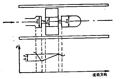
Figure 3-3 Principle of Hydraulic Balance
(3) Pre-Extender
The pre-spreader consists of a magneto-electric inductive converter and an extended shaping circuit. The schematic diagram is shown in Figure 3-4.
Magneto-electric converters usually use magneto-resistive type, which consists of permanent magnetic steel and externally wound induction coils. When the fluid passes through the slewing wheel, the reluctance is the lowest when the blade is directly under the permanent magnet, and the reluctance is the greatest when the gap between the two blades is below the magnet. The turbine travels and constantly changes the magnetic flux of the magnetic circuit, causing changes in the coil. The induced potential is fed into the extended shaping circuit as a pulse signal.
The frequency of the output pulse is proportional to the flow through the flowmeter, and its share factor K is
K =  ? (3-1)
Where f - turbine meter output pulse frequency;
Qv - flow through the flowmeter.
This share factor is also called the meter factor of the turbine flow meter.
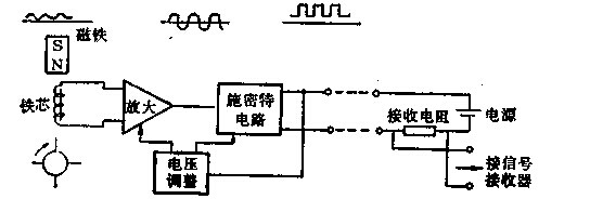
Figure 3-4 Schematic diagram of turbine flowmeter preamplifier
(4) Signal admission and manifestation
The signal receiver is composed of a coefficient corrector, a summator, and a frequency converter. The effect of this method is to convert the pulse signal sent from the pre-spreader into an accumulated flow and an instantaneous flow and to show it. ?
Construction silicone sealant,Special silicone sealant for insulation integrated board,Special silicone sealant for doors and windows
Shandong Gufeng Technology Co., LTD. , https://www.gfkjgs.com