
The speed sensor is a sensor that converts the rotational speed of a rotating object into a power output . The speed sensor is an indirect measuring device and can be manufactured by mechanical, electrical, magnetic, optical and hybrid methods. Depending on the form of the signal, the speed sensor can be divided into analog and digital.
The speed sensor is made up of a magneto-sensitive resistor as an inductive component and is a new type of speed sensor. The core component uses a magnetoresistive resistor as the sensing component, and the new signal processing circuit reduces the noise and improves the function. By comparing with the output waveform of other types of tooth speed sensors, the measured error of the rotational speed is extremely small and the linear characteristics are very consistent. The sensing object is magnetic material or magnetic conductive material such as magnetic steel, iron and electrical steel. When the object is magnetized or magnetized with protrusions (or depressions), as the object is rotated, the sensor outputs a pulse signal related to the rotation frequency to achieve the purpose of detecting the speed or displacement.
The gear speed sensor has the following features:
High sensitivity, high reliability, long life, long trigger distance
Signal trigger is iron (soft) magnetic material
Can achieve long-distance transmission anti-electromagnetic interference ability
Good impact resistance and shock resistance [1]
Parameter Description
Note: 1. Gear size parameters: gear outer diameter: 99.3mm; number of teeth: 60; modulus: 1.57 (The above dimensions are only one example, and the modulus is 0.5 to 2).
2. When installing the sensor, make the red LED of the tail and the root of the lead wire perpendicular to the gear plane.
3. The sensor lead wires are: brown for the power line; black for the ground line; blue for the signal output line.
Due to its ease of installation and use, it has good versatility and has been widely used in various fields. Especially in low-speed or ultra-low-speed non-contact detection, there are features that other sensors can't achieve. This feature fills the range of domestic blank magnetoelectric sensor speed measurement.
50-5000Hz. (The detection distance is only 0.5mm; the proximity switch cannot detect small mold teeth); in the medium and high speed non-contact detection, it can directly replace the Hall switch.
4. Detection distance: 0.5-2.0mm (A3 steel, electrical steel)
External magnet: 0.5--10mm
5. Gear modulus: m≥1
Gear material: A3 steel, electrical steel 120 ° C
6. Output signal:
Waveform: rectangular wave
Amplitude: near supply voltage
7. Environmental conditions:
Temperature: -40 ° C ~ 125 ° C [1]
Relative humidity: ≤85%
4. Selection guide:
PR-970-Bâ–¡â–¡-Câ–¡â–¡-Dâ–¡â–¡-Eâ–¡â–¡
Description:
B: Shell length C: Thread size D: Lead way E: Cable length
Sensor length: Bâ–¡â–¡
0 1:65mm 0 2:80mm 0 3:120mm 04: Customized
Installation thread: Câ–¡â–¡
01: M16*1. 02: Customer specified
03: M12*1 04: M10*1
05: M18*1.5
Lead mode Dâ–¡â–¡
00: Direct lead (waterproof type) 01: Aviation plug
Cable length Eâ–¡â–¡
01: Line length one meter 02: Line length two meters
03: Three meters and so on
Example:
PR970-B02-C02-D00-E02
Indicates 117mm long, M16*1 thread, direct lead, line length 2m
5. Wiring method: aerial plug or direct outlet
Red: 24V DC (12-25V DC)
Black: COM
Color line: signal output
Main functions and features
Princeton Optics is a world-renowned optical instrument; the PR-870 uses the principle of laser reflection to obtain the signal of the rotor's rotation and measure the rotor's speed. It features high resolution, long distance, wide practical range, wide frequency response and high reliability. Built-in amplification shaping circuit, the output is a square wave signal with stable amplitude, which can realize long-distance transmission.
Appearance
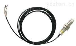
The sensor housing is made of stainless steel.
The waterproof structure is simple, the pressure resistance is strong, the seal is reliable, and no waterproof glue is used.
Applications
Because the sensor housing is made of stainless steel, the sensor is rugged and durable, mainly used in the test environment and vibration (such as: engine, etc.). Used to measure speed, cycle, speed.
Technical indicators
Working voltage: + 10-36v
Operating temperature: -40 to +80
Output signal: high level is similar to the power supply voltage; low level <0.3V, square wave.
Response frequency: 0.1HZ to 20KHz
Resolution film number: >0.5
Use humidity: <95% RH
Output current: <30 mA
Protection form: limited and short circuit protection
Trigger form: reflective strip
Insulation resistance: >50MΩ
Application distance: 2mm-600mm
Housing material: stainless steel
Length 65mm, diameter 18mm, wiring: brown 24V, blue negative, black signal
1 Overview:
The airborne HZ-860 magnetoelectric speed sensor can convert the angular displacement into an electrical signal for counter counting. As long as it is non-contact, it can measure various magnetic conductive materials such as gears, impellers, holes with holes (or slots, screws). Speed ​​and line speed.
The sensor has the advantages of small volume, strong and reliable, long life, no need of power supply and lubricating oil, and can be used with general secondary instruments.
2, technical parameters
1, the output waveform: approximate sine wave (≥ 50r / min)
2. Output signal amplitude:
≥300mv at 50r/min. Sensor core and measured gear tip clearance δ=0.5~1.2mm
The measured gear modulus m = 2
Gear Z = 60
Material electrical steel
The magnitude of the signal is proportional to the speed and inversely proportional to the size of the core and the tip clearance.
3, measuring range: 20 ~ 10000Hz
4, use time: continuous use
5, working environment: temperature -20 ~ +180 ° C
6, output form: X12K4P four-pin plug
7. Dimensions: Outer diameter: M12X1, M16×1; M18×1.5 total length 80mm; M20X1.5
8, weight: about 120g (excluding the output wire)
3, outline drawing:
Plug terminals 1, 4 connected to the signal output line
4, the use of precautions
1. When installing, the sensor housing M20×1.5 or other specifications of the thread shall not be damaged. The hex nut shall rotate freely. After the hex nut is tight, there shall be no looseness.
2. It is advisable to install the gear to be tested without contact with the sensor. It is hoped that the gap δ can be minimized to increase the amplitude of the output signal.
5, single set
1, magnetic speed sensor 1
2, cable line 2 meters
3, 1 part of the manual
4. 1 certificate of conformity
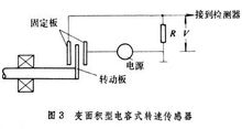
Capacitive sensors are available in both area and medium variations. In Fig. 3, the principle of the area change type is shown. The capacitive speed sensor is composed of two fixed metal plates and a movable metal plate connected to the rotating shaft. Movable metal plate is in power
 Speed ​​sensor
The position with the largest capacity is in the position with the smallest capacitance when the rotating shaft is rotated by 180°. The rate of change of the capacitance is the speed. The measurement signal of the rotational speed can be obtained by DC excitation, AC excitation, and an oscillation tank that constitutes the oscillator with a variable capacitance. The dielectric variation is formed by embedding a high dielectric constant movable plate between two fixed electrode plates of the capacitor. The movable medium plate is connected to the rotating shaft. As the rotating shaft rotates, the dielectric constant between the capacitor plates periodically changes to cause a periodic change in the capacitance, the rate of which is equal to the rotational speed of the rotating shaft.
It is a variable reluctance sensor. Three basic types of variable reluctance sensors, inductors
 Speed ​​sensor
Type sensors, transformer sensors and eddy current sensors can be used as speed sensors. Inductive speed sensors are widely used, which use the flux change to generate an induced potential whose magnitude depends on the rate at which the flux changes. These sensors are divided into open magnetic circuit and closed magnetic circuit according to different structures. The open magnetic speed sensor (Fig. 4a) has a relatively simple structure and a small output signal, which is not suitable for use in severe vibration situations. The closed magnetic path speed sensor consists of an external gear, an internal gear, a coil and a permanent magnet mounted on the rotating shaft (Fig. 4b). The inner and outer gears have the same number of teeth. When the rotating shaft is connected to the shaft to be tested and rotated together, due to the relative movement of the inner and outer gears, a magnetoresistance change occurs, and an alternating current induced potential is generated in the coil. The corresponding speed value can be measured by measuring the magnitude of the potential.
Most of them output pulse signals (approx. sine waves or rectangular waves). Methods for measuring the rotational speed of a pulse signal include a frequency integration method (that is, an F/V conversion method whose direct result is voltage or current), and a frequency algorithm (the direct result is a number).
In automation technology, rotational motion speed is measured more, and linear motion speed is often measured indirectly by rotational speed. The DC tachogenerator converts the rotational speed into an electrical signal. The tachometer requires a linear relationship between the output voltage and the speed, and requires a steep output voltage and good time and temperature stability.
The speed measuring machine can be generally divided into two types: direct current and alternating current. The rotary speed sensor is in direct contact with moving objects. When the moving object comes into contact with the rotary speed sensor, the friction causes the roller of the sensor to rotate. A rotating pulse sensor mounted on the roller sends out a series of pulses. Each pulse represents a certain distance value so that the line speed can be measured. In the electromagnetic induction type, the gear is mounted on the rotating shaft, and the outer side is the electromagnetic coil. The rotation is due to the passage of the tooth gap, and the voltage of the square wave is obtained, and then the rotational speed is calculated.
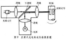
The rotary speed sensor has no direct contact with the moving object, and the edge of the blade of the impeller is coated with a reflective film. When the fluid flows, the impeller rotates. When the impeller rotates, the optical fiber transmits and reflects once, generating an electric pulse signal. The speed can be calculated from the number of pulses detected.
The gear material is made of a metal material with a large magnetic permeability, such as 45 steel.
The tooth shape is involute tooth shape, the distance between the tooth and the tooth and the width of the tooth have a great influence on the speed measurement. When the distance between the tooth and the tooth is too small, the sensor may have no output, which seriously affects the measurement, so the tooth shape should be as required. machining.
Figure 4 speed measuring gear structure diagram
Gear modulus: 2 ~ 4 tooth width b: greater than 5mm
m= = =
h=2.25×m
m: modulus
z: number of teeth
p: pitch
Refer to Figure 2 for sensor installation. A gear made of a magnetically permeable material (such as iron, steel, etc.) is mounted on the shaft to be measured, and the gear is machined into involute teeth with a modulus greater than two. Hall, magnetoresistive or eddy current sensors are mounted on the speed bracket and are radially aligned with the gears. The installation clearance is between 0.5 and 2 mm. The signal output cable of the sensor is a four-core shielded cable.
Lead description: red 24V, black com, yellow, signal output 1, green signal output 2,
The measurement of the rotational speed of the wind turbine shaft, under the slight wind, the shaft of the generator will rotate. The ZLS-Px angle sensor can monitor the real-time non-contact and feedback the data to ensure stability.
The workpiece processing speed monitoring, real-time monitoring of the workpiece speed on the CNC machine, helps the precision machining of the workpiece.
Steel pipe coating speed monitoring. Real-time monitoring of the coating speed of the steel pipe to ensure uniform paint. [2]
Prepainted Guardrail
The sprayed plastic guardrail adopts heavy anti-corrosion treatment, the internal coating is hot-dip galvanized layer, and the surface coating is made of all-polyester powder coating, which is firmly integrated with the substrate by electrostatic spraying. It has a strong ability to absorb collision energy and
has a good sight-inducing function.


| Product Name | Prepainted Highway Guardrail |
|
Material |
Q235,Q345 |
|
Surface Treatment |
hot dip galvanized,color coated |
|
Zinc Coating |
350g-1220g/square meter |
| Length |
4320/4130mm |
| Width |
2.5mm-4mm |
|
wave height |
81-85mm |
|
wave width |
310-315mm(W Beam) / 506mm(Thrie Beam |
|
Standard |
National Standard/American Standard/European standard |
|
Capacity |
100,000metric tons per year |
Prepainted Guardrail,Prepainted Highway Guardrail,Prepainted Guardrail
Shandong Hengfeng Group , https://www.luhengfeng.com